Use the Overall Geometry form to input the horizontal geometry for the superstructure. A maximum of two horizontal curves is allowed.
TIP: After completing input on this form, click the Define menu > Spans command or the Define Spans button and choose Deck Span Data 1, Deck Span Data 2, or Deck Span Data 3 to proceed to the next step in building the bridge model.
The Overall Geometry form includes the following three areas:
Origin data may be supplied by the user, or default values of 10000.00, 10000.00 will be supplied. Fork or ‘Y’ structures or structures with more than two curves must be analyzed by dividing the structure into several models.
Origin X and Origin Y Coordinates edit box. The ‘X’ and ‘Y’ coordinates of the beginning point of the geometry data specified on this form.
Tangent or BC to P1 Bearing edit box. If the bridge is straight, only the tangent bearing (Deg, Min, Sec) is required. If the structure is curved, enter the bearing of the BC to PI and the remainder of the curve data required (see below).
Rotation Angle (Degrees) edit box. If the Apply Standard Bridge Layout Rotation item on the Control Data form is Yes, the user may specify the angle the structure is to be rotated (clockwise as positive). If no value is specified, the program will apply the standard or default rotation. If a value is specified, the program will rotate the structure based on the entered angle.
Curve Data parameters. A maximum of two curves can be input. Zero radius curves are not permitted. Tangent bearings for single curves resulting in an internal angle (i.e., delta) equal to or greater than 180 degrees are not permitted. Negative stationing is not permitted.
No column. The program specifies the curve number in this column. If only one curve is required, omit the input for the second curve.
Direction column. Specify if the curve is deflected to the left (L) or right (R) as viewed looking ahead on stationing.
Radius column. Specify the radius of the centerline of the bridge in feet
Begin Station column. Specify the distance in feet of the beginning station for the curve from the start of the bridge.
Bearing (P1 to EC) column. Specify the tangent bearing (Deg., Min, Sec) from the point of intersection (PI) to the end of curve (EC).
Abutment parameters. The abutment data is used to specify the abutment number, location, geometry and support condition at the abutment.
Abut No. column. Supply the beginning abutment number or use the default value in the No 1 record/row. Supply the ending abutment number or use the default value in the No 2 record/row. The other selections made for record/row (Station, Elevation, Bearing and so forth) apply to the beginning or ending abutment.
Station column. Specify, to the nearest tenth-foot, the location of the abutment station from the centerline of the beginning Abutment. Stationing must increase from the beginning abutment to the end abutment.
Elevation column. Specify the actual elevation at the center of gravity of the superstructure in feet or assume an elevation to establish the datum. Only one reference datum is allowed. Abutments and bents must use the same reference datum. Zero elevation is not permitted.
Bearing column. Specify the bearing (Deg, Min, Sec) of the abutment centerline or leave this field blank. When this field is left blank, the abutment centerline bearing will be assumed to be normal to the superstructure centerline (radial on a curved alignment). The bearings at the abutments and bent centerline may be specified in either direction. Bearing specifications resulting in 90 degree skews are not permitted. Values greater than 90 degrees, or 59 min., or 59 sec. are not accepted.
Releases - Release Trans., Release Long., Release Vertical, Release Moment columns. Click the drop-down list and choose Free or Fixed.
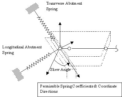
Two of the six support degrees of freedom at the abutment are assumed to be released, as shown in the following figure.

The options provide control over three of the four remaining degrees of freedom (i.e., transverse and longitudinal forces, and torsional moment about the superstructure center of gravity). Currently, two degrees of freedom (i.e., transverse and longitudinal forces) may also be described, as shown in the following figure:

Abutment force releases or forces for fixed condition are shown in the following figure:

See Also
BAG - Bridge Analysis Generator
|
Access the Overall Geometry form as follows:
|