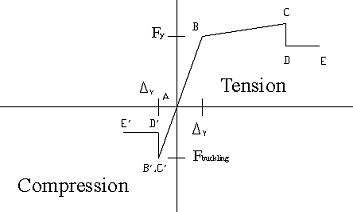
Steel Axial Hinge - Default Hinge Features:
Slope between points B and C is taken as 3% strain hardening
Hinge length assumption for Dy is the length of the member
Initial compression slope is taken to be the same as the initial tension slope
Points C, D and E are based on FEMA 273 Table 5.8, Braces in Tension
Points C’, D’ and E’ are based on FEMA 273 Table 5.8, Braces in Compression, Item C
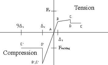
Concrete Axial Hinge - Default Hinge Features:
Py = As fy
Pc = 0.85 Ac f’c
Slope between points B and C is taken as 10% total strain hardening for steel
Hinge length assumption for Dy is based on the full length
Point B, C, D and E based on FEMA 273 Table 5.8, Braces in Tension
Point B’ = Pc
Point E’ taken as 9Dy

Steel Shear Hinge - Default Hinge Features:
Slope between points B and C is taken as 3% strain hardening
Dy = 0.01 radians per Note 3 in FEMA 273 Table 5.8
Points C, D and E based on FEMA 273 Table 5.8, Link Beam, Item a

Concrete Shear Hinge - Default Hinge Features:
Slope between points B and C is taken as 10% total strain hardening for steel
Vy = 2 As (f’c) ^ ½ + fy Asv d
Points C, D and E are based on ATC-40 Table 9.12, Item 2, average of the two rows labeled ”r;Conventional longitudinal reinforcement” and ”r;Conforming transverse reinforcement”
Steel Moment Hinge and Steel P-M-M Hinge

Steel Moment Hinge and Steel P-M-M Hinge - Default Hinge Features:
Slope between points B and C is taken as 3% strain hardening
qy based on FEMA 273, equation 5-1 and 5-2
Points C, D and E are based on FEMA 273 Table 5.4, for b / 2tf < 52 / (Fyc) ^ 1/2
P-M-M curve is for M3 (major moment) and is taken to be the same as the Moment curve in conjunction with the definition of Axial–Moment interaction curves.
Concrete Moment Hinge and Concrete P-M-M Hinge

Concrete Moment Hinge and Concrete P-M-M Hinge - Default Hinge Features:
Slope between points B and C is taken as 10% total strain hardening for steel
q = 0, since it is not needed
Points C, D and E are based on ATC-40, Table 9.6. The four conforming transverse reinforcing rows of the table are averaged.
My is based on reinforcement provided, otherwise it is based on minimum allowable reinforcement.
P-M-M curve is for M3 (major moment) and is taken to be the same as the Moment curve in conjunction with the definition of Axial–Moment interaction curves.
