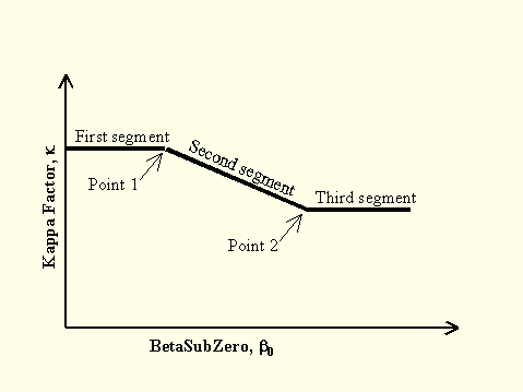
Override Structural Behavior Type Form

  1. Specify  values for BetaSubZero (b0) and the Kappa Factor at the beginning of the second segment in the Point 1 area.

  2. Specify values for BetaSubZero (b0) and the Kappa Factor at the end of the second segment in the Point 2 area.

Reset Defaults button. Click this button to restore the program default values for all parameters.


See Also

Nonlinear Static (Pushover) Analysis

Hinge Properties

Frame Hinge Property Data

Hinge Interaction Surface for {Property Name} Interacting {Hinge Type}

Curve Interaction Surface Definition For Property Name Form

Assign Frame Hinges (Pushover)

Pushover Curve

Override Axis Labels And Range


Access the Override Structural Behavior Type form as follows:


Method 1 - This method can be used to specify parameters for displaying a pushover curve before a static nonlinear analysis has been run.

  1. Click the Define menu > Pushover Parameters Sets> ATC 40 Capacity Spectrum command to display the Parameters for ATC 40 Capacity Spectrum form.

  2. Click the Add New Parameters, button, or select a previously defined parameters set and click the  Add Copy of Parameters, or Modify/Show Parameters button, to display the Parameters for ATC 40 Capacity Spectrum form,

  3. Select the User option in the Damping Parameters Definition area and click the Modify/Show button to display the Override Structural Behavior Type form.

Method 2 - Use this method to display a pushover curve after an analysis has been run.

  1. Define a static, nonlinear load case whose Load Application type is Displacement Control and whose Results Saved type is Multiple States; run a pushover analysis.

  2. Click the Display menu > Show Static Pushover Curve command to display the Pushover Curve form.

  3. Choose the Static Nonlinear Case and select ATC-40 Capacity Spectrum from the Plot Type drop-down list.

  4. Click the Add New Parameters, Add Copy of Parameters, or Modify/Show Parameters button to display the Parameters for ATC 40 Capacity Spectrum form.

  5. Select the User option in the Damping Parameters Definition area and click the Modify/Show button to display the Override Structural Behavior Type form.

Method 3 - Use this method to save the parameters specified for displaying a pushover curve as a Named Set for reuse in the future.

  1. Define a static, nonlinear load case whose Load Application type is Displacement Control and whose Results Saved type is Multiple States; run a pushover analysis.

  1. Click the Define menu > Named Sets > Pushover Named Sets command to display the Define Pushover Named Sets form.

  2. Click the Add New Named Set button, or highlight a previously defined named set and click the Add Copy of Named Set or Modify/Show Named Set button, to display the Pushover Named Set Data form.

  3. Choose ATC-40 Capacity Spectrum from the Plot Type drop-down list, choose the Static Nonlinear Case, and select the Plot Parameters from the drop-down list.

  4. Click the Add New Parameters, Add Copy of Parameters or Modify/Show Parameters button to display the Parameters for ATC 40 Capacity Spectrum form.

  5. Select the User option in the Damping Parameters Definition area and click the Modify/Show button to display the Override Structural Behavior Type form.