Draw Beam/Column/Brace Objects
Form: Properties of Object
Use the Draw menu > Draw Beam/Column/Brace Objects command or click one of the five buttons shown in this topic to draw frame objects. When the menu command is used, a menu of five subcommands displays.
-
Set the View. Some drawing tools do not function in some views. The views that can be used with a particular tool are indicated by the parenthetic information in the command name. That is, the Draw menu > Draw Beam/Column/Brace Objects > Draw Beam/Column/Brace (Plan, Elev, 3D) command can be used in any view—Plan, Elevation or 3D—while the Draw menu > Draw Beam/Column/Brace Objects > Quick Draw Beams/Columns (Plan, 3D) command can be used in a Plan or 3D view only. If a particular button does not appear to function, try changing the View setting.
TIP: When in a Plan view, set the Similar To drop-down list on the right side of the Status bar to Similar Stories or All Stories to quickly add frame objects, such as columns, to multiple stories simultaneously. Conversely, to add frame objects to one story only, be sure to set this drop-down list to One Story.
-
Click the Draw menu > Draw Beam/Column/Brace Objects command to display the list of subcommands. Click a subcommand or its associated toolbar button to display the Properties of Object form for the selected type of frame object. Use the options on the Properties of Object form to specify properties and control placement of frame objects for efficient integration into the model.
-
Draw the specified frame object as follows:
-
-
Left click once at the beginning of the frame.
-
Drag the mouse to the end of the frame and left click again. Note that as the mouse is dragged, a dashed line is visible, indicating the current extent of the frame object.
-
Left click once on the end point of the frame object to draw another frame object starting from the end of the first object; continue as needed. Double left click or single left click and depress the Enter key on the keyboard to terminate the drawing of the next frame.
When using this command in an elevation view or 3D view, if a frame object is drawn that crosses story levels, ETABS immediately breaks the object at the story levels. For example, if a frame object is drawn that has its top at the 4th story level and it bottom at the 2nd story level, ETABS immediately breaks the object into two objects with the break point at the 3rd story level.
The columns (vertical frame objects) extend from the story level where they were drawn to the story level below, and, of course, also to other story levels if the similar stories feature in the ETABS status bar has been activated.
-
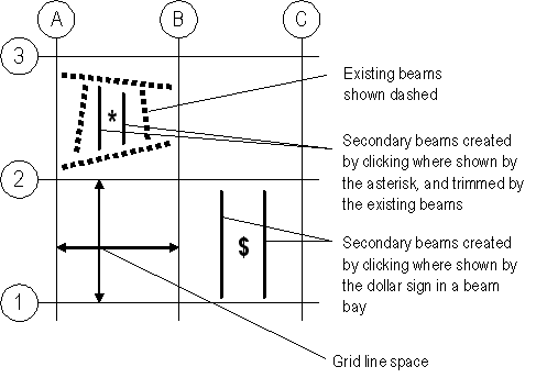
The grid line space is defined by four adjacent intersecting grid lines. If beams are already in the grid line space, the spacing and extent (length) of the secondary beams is based on the existing beams rather than the grid lines. The figure below shows an example of a grid line space and secondary beams. Note that secondary beams are not included on the grid lines.

-
-
Click the Draw menu > Draw Beam/Column/Brace Objects > Quick Draw Braces (Plan, Elev, 3D) command or button  . Use this command to quickly draw brace elements in a space bounded by two adjacent grid lines (from the same coordinate/grid system) and two adjacent story levels.
-
-
Click inside the space created by the intersection of two adjacent grid lines (from the same coordinate/grid system) and two adjacent story levels.
-
Alternatively, depress and hold down the left mouse button. While keeping the left button depressed, drag the mouse to "rubber band" a window around one or more grid line/story level spaces. Then release the left mouse button. Braces are automatically placed in each grid line/story level space within the region that is fully included in the "rubber band" window. The term grid line/story level space in this paragraph means the space created by the intersection of two adjacent grid lines (from the same coordinate/grid system) and two adjacent story levels.
-
Exit any of the drawing tools by clicking the Select Pointer button  or the Draw menu > Select Object command.
See Also
Snap Options
Drawing Constraints in ETABS
Tolerances
Graphics Preferences
 .
.